 |
|||||||||||||||||||||||||||||||||||||||||||||||||||||||||||||||||||||||||||||||||||||||||||||||
| About IGR | |||||||||||||||||||||||||||||||||||||||||||||||||||||||||||||||||||||||||||||||||||||||||||||||
| |
|||||||||||||||||||||||||||||||||||||||||||||||||||||||||||||||||||||||||||||||||||||||||||||||
The home and office digital appliances such as PCs, copiers and printers all use capacitor type power suppliers for voltage stabilization, and noise eliminators or filters. In addition, the increased scale of electric cables and increasing capacitance between cable and ground, lead to increased leakage current toward ground. The present situation is that earth leakage breakers (Io ELB) do not properly operate and in order to find the cause of leakage or the malfunction of the breaker, all the equipments must be unplugged and measure the insulation resistance with the Megger tool. In actual, it is very difficult or even impossible to shut down the equipments and use the Megger to measure insulation resistance and even if tested this way, there will be a lot of waste in personnel and cost because the equipments must be fully powered off.
The inverters, which are widely used in washers, air conditioners, elevators etc due to their energy efficiency and detail control function, cause a lot of harmonics leakage current. This leakage current may flow through the wires of the building and thus cause malfunction to the connected appliances. In the control rooms of factories, substations, IDC center powered from UPS, a large amount of leakage current is released and most of the time, the conventional leakage breaker(Io ELB) cannot handle the leakage and thus malfunction. Therefore, in most control rooms the leakage breaker(Io ELB) is either taken away or even never installed from the beginning, thus install MCCB instead of ELB. This is a very dangerous situation as resistive leakage current can lead to fire in these facilities. The earth leakage breakers(ELB) operates based on Io(I zero), and therefore in the digital world of today, the breakers does not function properly in world-wide.
Therefore, our company has developed an IGR leakage breaker which can operate at the amount of resistive leakage current properly, but will not operate at capacitive leakage current properly. The innovative IGR breaker will operate more sensitively to effective factor of resistive leakage current than to non-effective factor of capacitive leakage current.
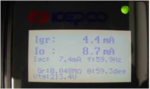
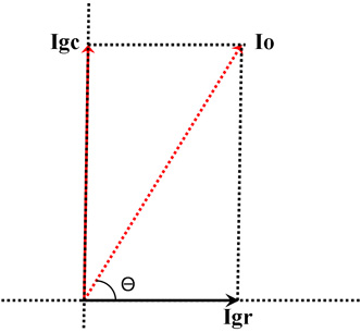
The need for Igr leakage measurement. : The Io, which is the leakage current measured by Zero Current Transfomer(Zct) is the vector sum of Igr (insulation Resistive leakage) an dIgc (capacitive leakage). Therefore Igc flows naturally on normal power line, main task in handling insulation resistance is to manage the effective leakage curren t, Igr.
Introduction of the patented technology analyzing leakage and measuring insulation resistance of circuits.
If the electric cables are inside a duct or underground conductor, cable inspection may be impossible. In the past, the insulation resistance was measured on a dead-line, but nowadays there are man y appliances which need to operate 24 hrs a day and therefore technologies which can measure leakage current on a live-line is continu ously being developed. Phase-difference and Igr measuring patented block diagram
The following diagram shows that the actual calculated value matches the measured value. 200volt 1phase 60Hz Area testing data picture
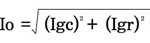
The following diagram helps to understand the vector disintegration formula.
100 Volt 3phase Delta 50Hz Area testing data picture
Performance Test Mode - Rø or Tø
- Rø and Tø
- (Rø or Tø) and C
The advantage of Igr leakage detection using phase difference measurements as our patented technology.
Therefore the US Leakage Breaker(UL943 Class A)’s for human protecting tipping point is set at 6mA±1mA.
Korea Elctricity Standard example The leakage current must be kept under 1mA where insulation resistance is difficult to be measured such as in the case of difficult powered-off at low voltage.
|
|||||||||||||||||||||||||||||||||||||||||||||||||||||||||||||||||||||||||||||||||||||||||||||||
| www.jsdata.co.kr Jaeshininfomation Co., Ltd |